Last Updated on Sep 29, 2026
Introduction – From Traditional Manufacturing to Automation
How did humans begin to transform ordinary processes into measurable and controlled systems, leading to automatic machines?
1. In Karnak in Upper Egypt around 1379 BC, people used water flow to control a physical process and create a measurable result.
In ancient Egypt, water clocks were used to measure the passage of time through controlled water flow. The oldest surviving water clock with physical archaeological evidence dates to approximately 1417–1379 BC, during the reign of Amenhotep III. Earlier textual evidence also associates water clocks with the Egyptian official Amenemhet during the 16th century BC. These early devices provided a practical example of using a measurable physical process to produce a controlled and repeatable result.[1]
2. The Antikythera Mechanism, around the end of the second century BCE, was an advanced astronomical device.
It was a portable box that showed calendar information and displayed both solar and lunar movements. It used gears and mechanical calculations to produce controlled outputs. The mechanism shows an early example of how mechanical components and gear trains could transform calculated information into controlled mechanical outputs.[2]
3. In medieval Europe, mechanical clocks were created using complex gear systems, eccentric gears, and pin-and-slot mechanisms to track the moon’s irregular orbit.
These designs show that Greek engineers / Hellenistic period were more skilled than the written records suggest. Complex geared mechanisms appeared again in medieval Europe, with mechanical clocks developing toward the end of the thirteenth century, leading to automatic timekeeping.[3]
Clock mechanism → mechanical machines → industrial machines → automated production
Mechanical engineering involves components such as cams, gears, linkages, and mechanisms.
These are all part of the organized way that automatic machines are used in industrial automation.
4 Germany played a central role in introducing and developing the Industrie 4.0 concept.
The term became publicly prominent around Hannover Messe 2011, where it was presented in the context of cyber-physical systems, the Internet of Things, and the future of manufacturing
In September 2010, a group decided to create a future project based on emerging trends like the Internet of Things, Internet of Services, and Cyber-Physical Systems (CPS). The project was called “cyber-physical production systems” and aimed to develop ambitious, forward-thinking projects with high economic and social value. In January 2011, a research alliance decided to name the project “INDUSTRIE 4.0: Germany as the lead provider of cyber-physical systems by 2020″[4]
Machine → senses → communicates → analyzes → acts
5. Robotics involves programmable mechanical systems.
The modern robot is a development of the mechanical mechanism into a programmable cyber-physical machine.
Mechanical Structure + Motors + Sensors + Controller + End Effector
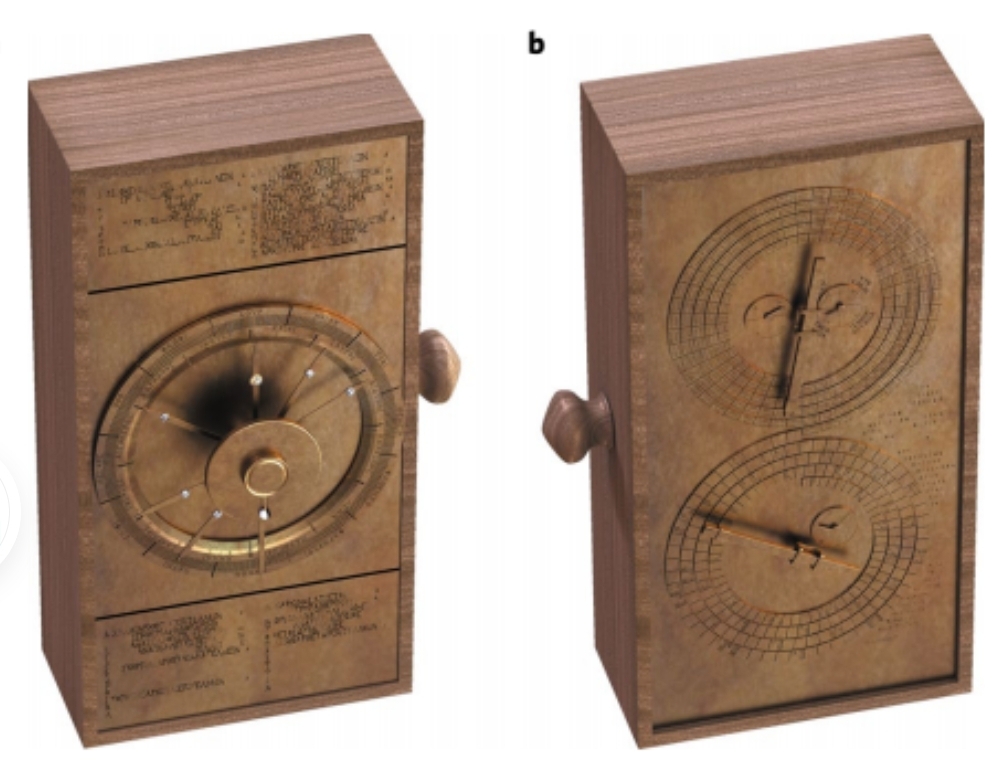
Fig. 1. Computer visualization of the Antikythera mechanism [2]
Why Mechanical Design Matters in Automation
Mechanical design is very important when creating automation systems, especially as industries become more advanced and connected. In modern manufacturing, machines do not operate independently. They are part of larger systems in which mechanical structures, control systems, and data exchange must work together smoothly.
Automation involves designing mechanical components and systems that perform specific functions within automated equipment. Engineers must consider real-world operating conditions because they directly affect system performance. Important factors include:
How loads and stresses are distributed during continuous operation
How accurately and consistently machines move during repeated tasks
How dimensional tolerances affect the fit and alignment of components
Environmental conditions such as heat, vibration, and contamination
Poor mechanical design can lead to problems such as component misalignment, premature wear, reduced accuracy, and unexpected system downtime. Addressing these issues during the design stage can help improve reliability and reduce costly problems after the system is put into operation.[5]

Fig. 2. Interior of an old factory showcasing vintage machines and equipment.
Source: Pexels
The Role of Mechanical Designers in Automated System Development
Mechanical designers develop mechanical systems that meet functional and production requirements. They use 3D CAD modeling to develop and evaluate designs, create digital or physical prototypes, identify potential problems, and select suitable materials according to the expected loads, temperature, and wear conditions.
1. Core Mechanical Design Workflow
A clear design process is important for developing reliable automation systems:
2. Requirement Definition
Understanding production requirements, operating speed, and system constraints.
3. Concept Development
Developing initial concepts and selecting suitable mechanisms based on feasibility and performance.
4. CAD Modeling and Simulation
Creating detailed 2D and 3D models and assemblies to evaluate geometry, detect clashes, and assess design performance before manufacturing.
5. Material and Component Selection
Selecting materials and components according to loading, wear, and manufacturing requirements.
6. Prototyping and Validation
Testing the design assumptions and making necessary modifications before final production.
Mechanical design provides the physical foundation for automation systems, supporting the integration of hardware, sensors, and control components. Early attention to mechanical design can help reduce design problems and improve the reliability and adaptability of automated systems.[5]
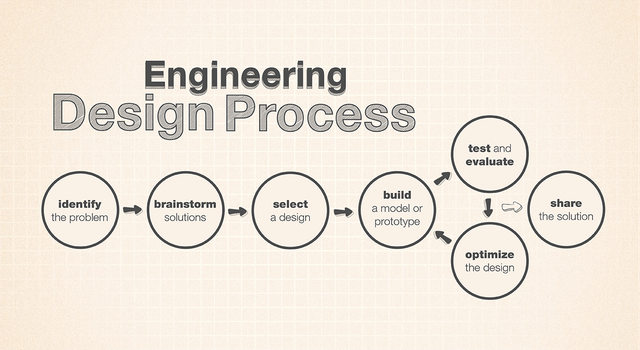
Fig. 3. File: Engineering Design Process – NASA-JPL-Caltech.png
Source: Wikimedia
The Evolution of Robots in Automated Technology
Robotic systems are widely used in automated manufacturing and assembly tasks, including picking and placing, material handling, and repetitive production operations. They are particularly useful for tasks that are dangerous, heavy, repetitive, or require high accuracy.
The history of modern robotics reflects technological developments that transformed earlier concepts of automation into modern robotic systems. This development has passed through several stages, from ancient automata and early service-robot concepts to the emergence of industrial robots and the expansion of service robotics.[6]
Robots can be classified into three main groups:
1. Manipulators
Serial manipulators: Include articulated, SCARA, Cartesian, cylindrical, and polar/spherical robots.
Parallel manipulators: Include Delta robots, which use parallel arms connected to a common platform and are widely used for high-speed pick-and-place applications.
Cable and soft manipulators: Use flexible cables or compliant structures for specialized manipulation tasks.
2. Mobile Robots
Mobile robots include wheeled, tracked, legged, flying, underwater, and water-surface robots.
3. Hybrid Robot Systems
Hybrid systems combine manipulation capabilities with mobile robotic platforms.[6]
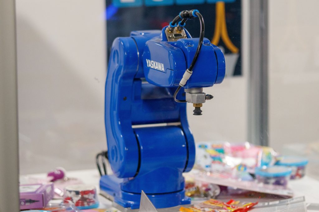
Fig. 4. A blue Yaskawa industrial robot arm on display, showcasing advanced technology and robotics.
Source: Pexels
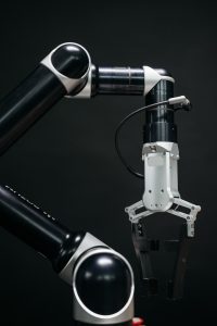
Fig. 5. Gripper robot
Source: Pexels
From 3D Model Design to a Robotic Gripper System
1. Design Requirements
The gripper design starts with the target object and the required grasping performance. Key objectives include grasp success, force stability, and robustness to variations in the grasping conditions.
2. 3D Gripper Design
For task-specific grasping, the finger geometry can be designed according to the target object’s shape. Fit2Form demonstrates a 3D generative approach that automatically produces parallel-jaw gripper finger geometries optimized for these grasping objectives.[7]
3. Simulation and Validation
The generated finger designs are evaluated through grasp simulation to assess their performance before physical implementation. The study also demonstrates the generated designs on a real robot, providing a link between digital gripper design and physical robotic grasping.[7]
Requirement → 3D Design → Design Review → Prototype → Manufacturing → Installation → Testing → Production.
Digital Design to the Factory Floor
1. Engineering Design
Engineering design transforms materials and components into finished products through processes such as machining, processing, and assembly. CAD/CAE tools support prototype development and manufacturing planning, including cutting, thermal, galvanic, fitting, and inspection operations.
2. Machining
Machining processes should be planned according to the part geometry, production requirements, available resources, and manufacturing experience. Proper process sequencing, positioning, and assembly are essential to achieve the required shape and precision.
3. Manufacturing
Manufacturing preparation includes defining suitable locating and setup methods for each component. CAD models and manufacturing drawings provide the geometric information needed to determine machining orientations, locating surfaces, and fixture arrangements.
4. Manufacturing Accuracy
Manufacturing accuracy describes how closely a finished component meets the dimensions and geometric requirements of its technical drawing. For robotic components such as gripper jaws and links, dimensional and geometric accuracy, surface quality, and proper positioning are important for reliable assembly and operation.[8]
5. Manufacturing Processes
After evaluating manufacturability, the manufacturing process can be planned based on the part drawing, material, geometry, production requirements, and available resources. The process may include preparation, machining, inspection, and assembly, with CAD systems supporting the selection of suitable manufacturing and setup methods.

Fig 6. Parallel arm gripping robot mechanism
Source: Author’s illustration
Practical Example: Developing an Automated Robotic Workstation
I will discuss two types of parallel robotic arm grippers to analyze the designs and determine how they perform in terms of stress and strain deformation.
Design Parameters: The first design (Compact Parallel) uses a pure parallel-motion trajectory across the full stroke. The second design (Extended Articulated) combines angular-arc motion with pivoting finger motion.
1. Categorization & Kinematic Breakdown
First Design (Parallel Linkage Gripper)
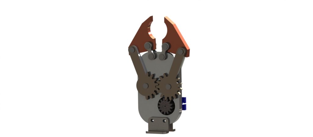
Fig. 7. Parallel-arm gripper robot, short gripper
Source: Author’s illustration
2. Second Design (Extended Linkage Angular/Parallel Gripper)

Fig. 8. Parallel-arm gripper robot, Extended arm
Source: Author’s illustration
3. Static Structural Analysis
A static structural analysis was performed in ANSYS using a **35 N gripping force** applied to the gripper finger. The analysis evaluates the resulting stress and deformation to assess the structural performance of the design under a representative loading condition.
The 35 N load represents a defined design case, while the actual gripping force depends on the workpiece weight, friction, acceleration, and safety factor.
4. Category: Articulated Dual-Pivot Linkage Gripper.
- Kinematics: Uses longer driven links combined with an upper central pivot block and constraining linkages connected to long finger arms. The power transmission originates from the gear mesh at the base, pushing the primary arms outward to pivot the upper fingers through a wider angular trajectory.
- Grasping Style: Encompassing angular motion with extended reach, suitable for larger or cylindrical workpieces.
5. Comparative Engineering Analysis
Stress Distribution: Uniform pressure across the jaw faces, or localized contact depending on the workpiece shape.
Robotic Arm: Tight pin and link tolerances help minimize play and backlash, while additional joints may increase deflection.
FEA Analysis: The following section presents the von Mises stress results from ANSYS Mechanical for the gripper jaw.
6. Key Simulation Data
Analysis Type: Static Structural 1 (ANSYS R17.2)
Short-arm gripper Result Type: Equivalent (von Mises) Stress
Maximum Stress: 2.027 MPa. The transition area along this curved profile acts as a stress concentration region due to bending moments during gripping.
Min Stress: 1.950 MPa, indicating relatively low stress in the less-loaded regions of the component.
To determine whether this value is beyond the limit, we evaluate it against the Yield Strength of the material assigned to the component in ANSYS.
Engineering Check: Since 2.027 MPa is an extremely small stress value compared to the yield strength of Aluminum 6061-T6 (276 MPa)
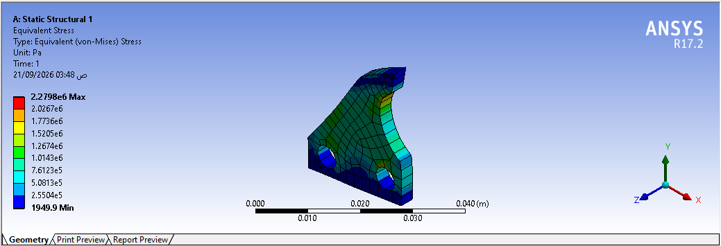
Fig. 9. Short gripper analysis in ANSYS
Source: Author
Key Simulation Data: Second Design
Analysis Type: Static Structural 2, Equivalent (von Mises) Stress
The maximum von Mises stress is 64.311 MPa, concentrated at the neck fillet/transition radius. This region acts as a geometric stress concentration due to the bending moment generated during gripping. For Aluminum 6061-T6, with a typical yield strength of approximately 276 MPa, the calculated stress remains below the yield strength for this load case, giving an approximate factor of safety of 4.29. Therefore, the design does not exceed the material yield strength under the applied loading condition.
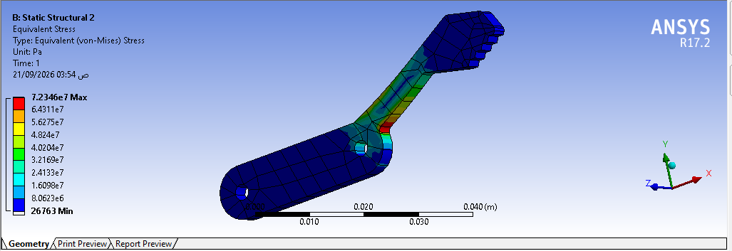
Fig 10 . Extended gripper analysis in ANSYS
Source: Author
Design Comparison: Design 1 vs. Design 2
Stress Distribution: Design 1 provides a more uniform load distribution, while Design 2 shows higher stress concentration at the inner neck fillet due to its longer moment arm.
| Feature |
Design 1 – Parallel Gripper
|
Design 2 – Dual-Pivot Gripper |
| Motion | Parallel movement
|
Angular/arc movement |
| Gripping | Higher gripping force
|
Enveloping grip |
| Main Advantage | Precision and rigid alignment
|
Extended reach and wider opening |
| Application | Flat/prismatic parts, pick-and-place, assembly | Round, large, or irregular parts |
Final Engineering Recommendation
Design 1: Suitable for precision pick-and-place, higher gripping force, and rigid alignment.
Design 2: Suitable for extended reach and gripping larger or irregular objects. Increasing the inner neck fillet radius can help reduce stress concentration.
| Design | Maxi Stress | Yield Strength | Approx FOS |
| Design 1 | 2.027 MPa | 276 MPa | 136.2 |
| Design 2 | 64.311 MPa | 276 MPa | 4.29 |
Conclusion – From Mechanical Design to Smart Manufacturing
Industrial automation depends on the integration of mechanical design, manufacturing, sensing, control, and digital technologies. Mechanical design provides the foundation for accurate, reliable, and repeatable automated systems.
This article presented a practical path from system requirements and 3D CAD to robotic gripper design, mechanical evaluation, manufacturing, and factory integration. The gripper example showed how different configurations affect motion, gripping behavior, reach, force transmission, and structural performance.
Moving from digital design to production requires attention to manufacturability, tolerances, materials, machining, assembly, inspection, and testing. CAD and simulation can help identify design issues before manufacturing and reduce physical modifications.
As manufacturing advances toward Industry 4.0, mechanical designers increasingly work with multidisciplinary teams to integrate mechanical systems, sensors, controls, data, and robotics. A strong mechanical design process remains essential for reliable and flexible automation.
FAQ
-
What is the role of mechanical design in robotic systems?
It defines grippers, fixtures, structures, and mechanical interfaces.
-
Why is 3D CAD important?
It supports design, clearance checks, and manufacturing preparation.
-
How are robot grippers designed?
Based on the workpiece, gripping force, payload, and application.
-
How does simulation help?
It evaluates motion, interference, and structural performance before manufacturing.
-
What are the main steps from design to manufacturing?
Design, CAD, simulation, manufacturing, assembly, and testing.
Reference:
- Cotterell, B., Dickson, F. P., & Kamminga, J. (1986). Ancient Egyptian water-clocks: A reappraisal. Journal of Archaeological Science, 13(1), 31–50. https://doi.org/10.1016/0305-4403(86)90025-7
- Seiradakis, J. H., & Edmunds, M. G. (2018). Our current knowledge of the Antikythera Mechanism. Nature Astronomy, 2, 35–42. https://doi.org/10.1038/s41550-017-0347-2
- Efstathiou, K., Efstathiou, M., & Basiakoulis, A. (2023). The artistic complexity of the Antikythera Mechanism: A comprehensive tutorial. Proceedings of the European Academy of Sciences and Arts, 2(1). https://doi.org/10.4081/peasa.2
- DFKI. (2021). Ten Years of INDUSTRIE 4.0 – Germany Driving Industrial AI as the Means to Future Value Creation. German Research Center for Artificial Intelligence.
- IDEA –Mechanical Design. Powerful Base for Automation Systems
https://ideagroupvn.com/mechanical-design-for-automation-systems/
- Carbone, G., & Laribi, M. A. (Eds.). (2022). Robot Design: From Theory to Service Applications. Springer. https://doi.org/10.1007/978-3-031-11128-0
- Ha, H., Agrawal, S., & Song, S. (2021). Fit2Form: 3D Generative Model for Robot Gripper Form Design. Proceedings of the 2020 Conference on Robot Learning, 155, 176–187.
- Ivanov, V., Evtuhov, A., Dehtiarov, I., & Trojanowska, J. (2025). Fundamentals of Manufacturing Engineering Using Digital Visualization. Springer. https://doi.org/10.1007/978-3-031-74360-3
Author Bio
 Kholoud Mostafa
Kholoud Mostafa is a Mechanical Engineer with experience in mechanical design, research and development, manufacturing, and product development. Her professional interests include mechanical design, 3D CAD modeling, thermal management, manufacturing systems, and engineering innovation. She has experience using engineering tools such as SolidWorks, AutoCAD, Inventor, and simulation software to support design and development projects.
LinkedIn