Last Updated on Jun 29, 2016
In computer switching circuits, in which the logical Boolean operation on data performed are called logic circuits or a circuit for performing the logical operations. A logic circuit consists of a number of a logic gates. In formal language a Logic circuits are the basic building blocks of real-world computers.
Basically logic circuits are electric circuit whose output depends upon the input in a way that can be expressed as a function in symbolic logic. A logic circuit has one or more binary inputs (capable of assuming either of two states, for example “on” or “off”) and a single binary output. Logic circuits that are used to perform particular functions are called as GATE. Hence Logic circuits are normally composed of gates. A combination of gates makes up a circuit. Basic logic circuits include the basic logic gates like AND gate, OR gate, and the NOT gate, which perform the logical functions AND, OR, and NOT.
In logic circuit Boolean constants 0 and 1 do not represent actual number but instead represent the state of a voltage variable. This state of voltage variable called the logic level. Some digital circuits can be extremely complex those type of Logic circuits can be built from any binary electric or electronic devices, including switches, relays, electron tubes, solid-state diodes, and transistors. The selection of these electronic devices is depends upon the application and logic circuit design requirements. They are connected in such a way that the circuit output is the reset of logic output. These types of logic circuits are called logic gates. The operation of and logic circuit is summarized in the form of binary numbers by a truth table. A truth table describes how a logic circuit output on the logic level present at the circuit inputs.
Modern technology has produced integrated circuits (ICs) or integrated logic circuits, modules that perform complex logical functions. A major use of logic circuits is in electronic digital computers. Similarly in fluid logic circuits have been developed whose function depends on the flow of a liquid or gas rather than on an electric current flow in the circuit.
Types of logic circuits:
Logic circuit for digital system is categorized into two main categories;
- Computational logic circuit
- Sequential logic circuit
Computational logic circuits:
Computational logic circuits consist of logic gates whose outputs at any time are determined directly from the present combination of inputs without regard to previous output.
Sequential logic circuits:
Sequential circuits employ memory elements i.e. binary cells in addition to logic gates. The output of an sequential circuits are a function of the inputs and the state of the memory elements. The state of an memory elements, in turn, is a function of previous outputs.
Logic Representation:
As we know that logic circuits are normally composed of ‘gates’. It is that the logic gates produce pulses of electrical current (1s and 0s). Below we are explaining about the logic representation techniques that help you to express the working of a logic circuit. There are three common ways in which to represent the working of a logic circuit.
- Truth Tables
- Logic Circuit Diagram
- Boolean Expression
We will discuss each herein and demonstrate ways to convert between them.
Truth Tables:
A truth table is a chart of Boolean values (1s and 0s) arranged to indicate the results (or outputs) of all possible inputs combinations. The lists of all possible inputs combination are arranged in columns on the left and the resultant outputs are listed in columns on the right side of the table. If there are n inputs then there are maximum 2n (2 to the power n) possible states or unique combination of inputs. For example with three inputs there are 23=8 possible combination of inputs.
| Inputs | Outputs | ||
| A | B | C | Y |
| 0 | 0 | 0 | 0 |
| 0 | 0 | 1 | 0 |
| 0 | 1 | 0 | 0 |
| 0 | 1 | 1 | 1 |
| 1 | 0 | 0 | 1 |
| 1 | 0 | 1 | 0 |
| 1 | 1 | 0 | 0 |
| 1 | 1 | 1 | 1 |
Logic Circuit Diagram:
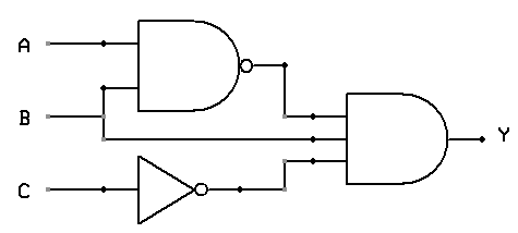
A logic circuit diagram uses the graphical representation or description of logic gates in combination to represent a logic expression. An example of logic circuit diagram, shows below with three inputs (A, B, and C) and one output (Y). The interpretation of this will become clear in the following sections.
Boolean Expression:
Boolean algebra can be used to write a logic expression in the form of an equation. There are a few symbols and operators that are uses to express the output of a logic circuit.
‘+’ means OR, So P+Q is same as P OR Q
‘*’ means AND, So P*Q is same as P AND Q
A ̅ means NOT A, Sometimes it is called complement of A
⨁ means XOR, So P ⨁ Q means P XOR Q
Application of Logic circuits:
In modern technology logic circuits are found in several high-tech devices including arithmetic logic units, computer memory and registers, multiplexers and decoder/encoder. Logic circuits are also used in upgraded technical microprocessors, some of which can contain over 100 million gates. Also, logic gates are the building blocks of digital electronics and are formed by the combination of transistors in order to realize some digital operations. Every digital product, including personal computers, mobile phones, tablets, calculators and digital watches also uses logic gates.
Also Read: Transistor as a switch theory with block diagram
Advantages of Logic circuits:
Logic circuits perform logical operations on the behalf of Boolean logics. Logic circuits are primarily implemented electronically using semiconductor diodes or transistors, but it can be constructed using different basic logic gates which are implemented by electromagnetic relays, fluidics, molecules, optics or even mechanical elements.
In real world technology are highly uses various types of logic circuits to solve the complex real time problems. There are different types of advantages those are provides an positive edge for using logic gates. Various advantages of logic circuits are as follows;
Also Check: C Programming Tutorials
- Logic circuits have the ability to rectify noise on the input that results in the signal not correctly switching from 0V to 5V for 0 and 1 respectively. This is an ability that desired in Logic circuits, and why they are commonly used throughout the industry.
- Since basic logics gates like AND, OR, NOT, TTL etc. are no more expensive so the use of logic gates is less expensive in design and use.
- Logic circuits are more precise representation of a signal can be obtained by using more binary digits to represent it.
- Modern technology uses logic circuits to be control the operation. The operations of logic circuits are controlled by software, so new functions to be added without changing hardware.
- The switching time is much faster than analog circuits.
Disadvantages of Logic circuits:
As logic circuits are the best utilities devices in the modern technology, but there have some disadvantages are as follows;
- Logic circuits uses more energy than other circuits like analog circuits to accomplish the same tasks resultant circuit produces more heat. This can be limit use of logic circuits.
For activation, logic circuits require power system i.e. portable or battery power systems which are limited in power.

 (Relay, Contactor, Switch And Timer)")
 : Introduction, Use, Example with Block diagrams")


